Reviewed by: Technical Engineering Department – TGB Group Published: September 2026 Technical review: September 2026
A slewing component is not always the root cause of the problems observed in a slewing system. In most installations, the slewing ring, the drive and the supporting structure are selected and calculated correctly as individual components, yet the assembly still develops uneven wear, excess play or rising rotational resistance once it is in service. In many cases, the reason is the same: the three elements were treated as separate parts rather than as a single system whose behaviour is determined by how they interact.
The supporting structure, the slewing ring and the drive form a chain. Loads and torque pass through every link, and a weakness or error at any interface affects the others. A perfectly specified slewing ring mounted on a structure that deflects under load will not behave as calculated. A correctly sized drive whose pinion is poorly meshed with the ring gear will wear prematurely regardless of its rating. The performance of the system is set not by the best component, but by the quality of the connections between them.
This article explains how the three elements interact, where the critical interfaces are, the integration errors that most often appear at each one, and how to avoid them during design rather than discover them in the field.
The three elements and the two interfaces
It is useful to picture a slewing system as three elements connected by two interfaces.
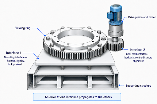
The three elements are the supporting structure that carries the system, the slewing ring that supports the loads and enables rotation, and the drive that transmits torque through a pinion meshing with the ring gear. The two interfaces are where integration succeeds or fails: the mounting interface between structure and ring, and the gear mesh interface between drive pinion and ring gear.
Most integration errors occur at these two interfaces, and most of them are introduced during design and assembly, not during operation. That is precisely why they are avoidable.
Interface 1: structure and slewing ring
The mounting interface determines how load is transferred from the slewing ring into the structure, and back. Three factors govern whether that transfer is uniform.
The first is surface flatness. An out-of-flat mounting surface forces the ring to deform when it is bolted down, distorting the raceway and concentrating load on a few rolling elements. The second is structural rigidity. Under load, the supporting structure deflects, and if it is not rigid enough to support the ring evenly, the load distribution inside the bearing changes while the machine works. The third is bolt preload. Uniform, correctly applied preload holds the interface together; uneven or insufficient preload reproduces the same distortion as an out-of-flat surface.
These three factors are closely linked and are covered in depth in our article on mounting tolerances and surface flatness in slewing rings. For the purposes of integration, the key point is that the structure is not a passive base. It is an active part of the load path, and its flatness, rigidity and bolted connection directly determine how the slewing ring performs.
A frequent and important nuance is that rigidity must be compatible across the assembly. The objective is not to make every element as stiff as possible, but to ensure that the structure, ring and connection deform in a controlled and balanced way, so that stress is not concentrated in the most rigid element. This is the same principle that applies when integrating planetary gearboxes in slewing systems.
Interface 2: slewing ring and drive
The gear mesh interface is where the drive pinion engages the ring gear to transmit torque. It is the interface most specific to slewing systems, and the one where integration errors are both common and damaging.
The central parameter is backlash: the clearance between the pinion teeth and the ring gear teeth. Backlash must be neither too small nor too large. Too little backlash makes the gears bind, generating friction, heat and accelerated wear, and in extreme cases jamming the rotation. Too much backlash allows the teeth to mesh poorly, producing impact between teeth under load, noise, tooth damage and accelerated wear. Correct backlash is a specified range, not a target of zero.
Backlash is set in a specific way that integration teams must respect. A slewing ring gear is never perfectly round; it has a high point of radial runout, the point of maximum eccentricity, which the manufacturer typically identifies with a mark on the ring. Backlash must be set at that high point, by adjusting the centre distance between the pinion and the ring gear. If backlash is set at any other point, the mesh will be too tight when the high point rotates into engagement, and the gears will bind once per revolution. The correct backlash value is commonly defined as a function of the gear module or supplied directly in the manufacturer’s installation documentation, with the exact figure specified for the gear in question.
Two further factors complete the interface. The centre distance between pinion and ring gear, which sets the backlash, must be held by a rigid and correctly positioned pinion mounting; if the pinion support deflects or shifts, the backlash changes in service. And the alignment of the pinion axis relative to the ring gear must be correct, so that the teeth make contact across their full width rather than on one edge.
How the elements interact
The reason integration deserves its own attention is that the three elements are not independent. A problem introduced at one point appears as a symptom somewhere else, which is what makes integration errors difficult to diagnose after the fact.
A structure that deflects under load changes the load distribution in the slewing ring, and that same deflection can move the ring gear relative to the pinion, changing the backlash. An out-of-flat mounting surface distorts the raceway and can also distort the gear, affecting the mesh. Loss of bolt preload allows micro-movement that shows up both as bearing wear and as variable backlash at the drive. A poorly meshed pinion overloads specific teeth and feeds vibration and shock back into both the ring and the structure.
In each case, the visible symptom — uneven wear, rising torque, noise, developing play — may appear at a different element from the one where the error originated. This is why integration must be considered as a whole. Treating a symptom at the bearing without checking the structure and the drive often means correcting the effect while leaving the cause in place.
Common integration errors and how to avoid them
Most integration problems trace back to a recognisable set of errors, each of which is avoidable in the design and assembly phase.
| Integration error | Consequence in service | How to avoid it |
|---|---|---|
| Out-of-flat mounting surface | Raceway distortion, uneven load, premature wear | Machine and verify flatness against the manufacturer’s limit |
| Insufficient or uneven structural rigidity | Load redistribution under load, accelerated wear | Evaluate structural deflection; design for compatible stiffness |
| Uneven or insufficient bolt preload | Micro-movement, variable backlash, raceway deformation | Apply specified preload with correct tightening sequence |
| Backlash set away from the high point of runout | Gears bind once per revolution, localised wear | Set backlash at the marked high point of radial runout |
| Backlash too small | Friction, heat, binding, accelerated tooth wear | Set backlash to the specified range for the gear module |
| Backlash too large | Tooth impact, noise, tooth damage | Set backlash to the specified range; check pinion mounting |
| Deflecting or mispositioned pinion support | Backlash changes in service, edge tooth contact | Mount the pinion on a rigid, correctly aligned support |
| Treating components as independent | Symptoms misdiagnosed, recurring failures | Design and validate the system as a whole |
The pattern across the table is consistent: integration errors are introduced early, are inexpensive to prevent at the design stage, and are costly to correct once the system is built and operating.
A practical sequence for correct integration
A structured approach reduces integration errors significantly:
- Define the system, not just the components. Establish the loads, moments, torque, duty cycle and environment for the assembly as a whole.
- Design the mounting interface deliberately. Specify flatness, roughness, structural rigidity and bolt preload as engineering requirements, not fabrication details.
- Verify the structure under load. Confirm that structural deflection is within acceptable limits and compatible with the ring and connection.
- Set the gear mesh correctly. Locate the high point of runout, set backlash to the specified range at that point through the centre distance, and verify pinion alignment.
- Check the interfaces after assembly. Re-verify flatness after bolting and backlash after the pinion is mounted, because preload and assembly can shift both.
- Treat the result as a system. Document the integration so that any later symptom can be traced to the interface where it originates.
Following this sequence does not add significant cost. It moves the effort to the phase where errors are cheapest to prevent.
What integration problems usually look like in the field
In many field cases, the first visible symptom is not described as an integration problem. It appears as rising rotational torque, repeated gear noise, uneven tooth wear, localised bearing wear or backlash that changes during rotation. These symptoms are also important when recognising wear in slewing systems, although their underlying cause may lie in the component itself or at one of its interfaces. These symptoms tend to lead inspection teams towards the bearing or the drive first, because that is where the symptom is visible. But the origin may be the mounting interface, the pinion support or the structure deflecting under load.
This is where the system perspective becomes practically necessary. A bearing replaced without checking the mounting surface and the structure will often develop the same wear pattern on the new ring. A drive repaired without addressing pinion alignment or backlash at the high point will reproduce the same gear noise. The symptom changes; the cause does not. Tracing integration problems to their source means looking at the interfaces, not just the components.
Where integration matters most
Integration discipline is important in every slewing application, but its impact grows where loads are high, where the structure is large or flexible, and where the drive transmits significant torque. Lifting and platform machinery, cranes, large positioners, solar tracking systems and heavy rotating equipment all combine substantial loads with structures that deflect and drives that must mesh precisely. In these systems, the difference between a correctly integrated assembly and an approximately integrated one is the difference between calculated service life and premature, hard-to-diagnose failure.
How TGB Group supports integration
With more than 30 years of experience in motion solutions, TGB Group’s in-house engineering department works with customers on the integration of slewing rings and slewing drives into their machines, not only on the selection of the individual components. This includes advising on the mounting interface, the structural requirements and the gear mesh, so that the assembly behaves as a system rather than as a set of separate parts.
Because the flatness limits, bolt specifications, backlash range and alignment requirements depend on the specific products, TGB provides these parameters in the technical documentation for the selected slewing ring and drive, and supports the engineering team in defining the interfaces correctly for the real operating conditions of the application.
If you are integrating a slewing ring and drive into a structure, or diagnosing a problem that may originate at one of the interfaces, TGB Group’s technical team can help. Contact our technical team to review the integration of your slewing system and define the interface requirements for your application.
Frequently asked questions about slewing system integration
Why do slewing systems fail at the interfaces rather than in the components?
Because the slewing ring, drive and structure are usually specified and calculated correctly as individual components, while the way they connect is treated as a secondary detail. Loads and torque pass through the mounting interface and the gear mesh, so an error at either interface affects the whole system. Many field problems originate at these connections rather than in a defective component.
How is backlash set between a slewing ring and a drive pinion?
Backlash is set at the high point of the ring gear’s radial runout, the point of maximum eccentricity, which the manufacturer typically marks on the ring. With that point in mesh, the centre distance between the pinion and the ring gear is adjusted until the backlash is within the specified range, commonly defined as a function of the gear module. Setting backlash anywhere else causes the gears to bind once per revolution when the high point rotates into engagement.
What happens if slewing drive backlash is too small or too large?
Too little backlash makes the gears bind, generating friction, heat and accelerated wear, and in extreme cases jamming the rotation. Too much backlash allows the teeth to mesh poorly, producing impact between teeth under load, noise, tooth damage and accelerated wear. Correct backlash is a specified range, set at the high point of runout, not a value of zero.
How does the supporting structure affect slewing ring performance?
The supporting structure is part of the load path, not a passive base. If the mounting surface is out of flat, the ring is distorted when bolted down. If the structure deflects under load, the load distribution inside the bearing changes during operation, and the ring gear can move relative to the pinion, changing the backlash. The structure’s flatness, rigidity and bolted connection directly determine how the slewing ring behaves.
Can a problem in the structure show up as a problem in the bearing or the drive?
Yes, and this is what makes integration errors hard to diagnose. A structure that deflects can cause uneven bearing wear and also change the gear backlash. Loss of bolt preload can appear as both bearing play and variable backlash. The visible symptom often appears at a different element from where the error originated, which is why the system must be checked as a whole rather than component by component.
Should the structure, slewing ring and drive be as rigid as possible?
Not necessarily. Rigidity must be compatible across the assembly. The objective is for the structure, ring and connection to deform in a controlled and balanced way, so that stress is not concentrated in the most rigid element. Over-stiffening one component in isolation can concentrate load rather than distribute it, which is why stiffness should be matched across the system.
When should slewing system integration be checked after assembly?
The interfaces should be re-checked after assembly because preload and the assembly process can shift them. Mounting surface flatness can change once the bolted joint is preloaded, and gear backlash can change once the pinion is mounted and the structure is loaded. On critical applications, verifying flatness after bolting and backlash after pinion mounting confirms that the integration is correct before the system enters service.
What information is needed to integrate a slewing ring and drive correctly?
The starting point is the load case and operating conditions for the assembly as a whole: axial and radial loads, tilting moment, torque, rotational speed, duty cycle and environment. From there, the mounting interface requirements (flatness, rigidity, bolt preload) and the gear mesh requirements (backlash range, centre distance, pinion alignment) are defined from the manufacturer’s documentation for the specific slewing ring and drive selected.